Continuity Equation Mass Transfer Continuity Equation Fluid Mechanics
Continuity Equation
This page provides the chapter on the continuity equation from the "DOE Fundamentals Handbook: Thermodynamics, Heat Transfer, and Fluid Flow," DOE-HDBK-1012/3-92, U.S. Department of Energy, June 1992.
Other related chapters from the "DOE Fundamentals Handbook: Thermodynamics, Heat Transfer, and Fluid Flow" can be seen to the right.
Continuity Equation
Understanding the quantities measured by the volumetric flow rate and mass flow rate is crucial to understanding other fluid flow topics. The continuity equation expresses the relationship between mass flow rates at different points in a fluid system under steady-state flow conditions.
Introduction
Fluid flow is an important part of most industrial processes; especially those involving the transfer of heat. Frequently, when it is desired to remove heat from the point at which it is generated, some type of fluid is involved in the heat transfer process. Examples of this are the cooling water circulated through a gasoline or diesel engine, the air flow past the windings of a motor, and the flow of water through the core of a nuclear reactor. Fluid flow systems are also commonly used to provide lubrication.
Fluid flow in the nuclear field can be complex and is not always subject to rigorous mathematical analysis. Unlike solids, the particles of fluids move through piping and components at different velocities and are often subjected to different accelerations.
Even though a detailed analysis of fluid flow can be extremely difficult, the basic concepts involved in fluid flow problems are fairly straightforward. These basic concepts can be applied in solving fluid flow problems through the use of simplifying assumptions and average values, where appropriate. Even though this type of analysis would not be sufficient in the engineering design of systems, it is very useful in understanding the operation of systems and predicting the approximate response of fluid systems to changes in operating parameters.
The basic principles of fluid flow include three concepts or principles; the first two of which the student has been exposed to in previous manuals. The first is the principle of momentum (leading to equations of fluid forces) which was covered in the manual on Classical Physics. The second is the conservation of energy (leading to the First Law of Thermodynamics) which was studied in thermodynamics. The third is the conservation of mass (leading to the continuity equation) which will be explained in this module.
Properties of Fluids
A fluid is any substance which flows because its particles are not rigidly attached to one another. This includes liquids, gases and even some materials which are normally considered solids, such as glass. Essentially, fluids are materials which have no repeating crystalline structure.
Several properties of fluids were discussed in the Thermodynamics section of this text. These included temperature, pressure, mass, specific volume and density. Temperature was defined as the relative measure of how hot or cold a material is. It can be used to predict the direction that heat will be transferred. Pressure was defined as the force per unit area. Common units for pressure are pounds force per square inch (psi). Mass was defined as the quantity of matter contained in a body and is to be distinguished from weight, which is measured by the pull of gravity on a body. The specific volume of a substance is the volume per unit mass of the substance. Typical units are ft3/lbm. Density, on the other hand, is the mass of a substance per unit volume. Typical units are lbm/ft3. Density and specific volume are the inverse of one another. Both density and specific volume are dependant on the temperature and somewhat on the pressure of the fluid. As the temperature of the fluid increases, the density decreases and the specific volume increases. Since liquids are considered incompressible, an increase in pressure will result in no change in density or specific volume of the liquid. In actuality, liquids can be slightly compressed at high pressures, resulting in a slight increase in density and a slight decrease in specific volume of the liquid.
Buoyancy
Buoyancy is defined as the tendency of a body to float or rise when submerged in a fluid. We all have had numerous opportunities of observing the buoyant effects of a liquid. When we go swimming, our bodies are held up almost entirely by the water. Wood, ice, and cork float on water. When we lift a rock from a stream bed, it suddenly seems heavier on emerging from the water. Boats rely on this buoyant force to stay afloat. The amount of this buoyant effect was first computed and stated by the Greek philosopher Archimedes. When a body is placed in a fluid, it is buoyed up by a force equal to the weight of the water that it displaces.
If a body weighs more than the liquid it displaces, it sinks but will appear to lose an amount of weight equal to that of the displaced liquid, as our rock. If the body weighs less than that of the displaced liquid, the body will rise to the surface eventually floating at such a depth that will displace a volume of liquid whose weight will just equal its own weight. A floating body displaces its own weight of the fluid in which it floats.
Compressibility
Compressibility is the measure of the change in volume a substance undergoes when a pressure is exerted on the substance. Liquids are generally considered to be incompressible. For instance, a pressure of 16,400 psig will cause a given volume of water to decrease by only 5% from its volume at atmospheric pressure. Gases on the other hand, are very compressible. The volume of a gas can be readily changed by exerting an external pressure on the gas.
PDH Classroom offers a continuing education course based on this continuity equation reference page. This course can be used to fulfill PDH credit requirements for maintaining your PE license.
Now that you've read this reference page, earn credit for it!

Relationship Between Depth and Pressure
Anyone who dives under the surface of the water notices that the pressure on his eardrums at a depth of even a few feet is noticeably greater than atmospheric pressure. Careful measurements show that the pressure of a liquid is directly proportional to the depth, and for a given depth the liquid exerts the same pressure in all directions.

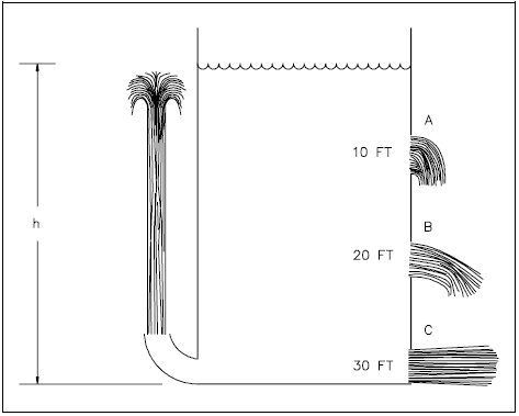
As shown in Figure 1 the pressure at different levels in the tank varies and this causes the fluid to leave the tank at varying velocities. Pressure was defined to be force per unit area. In the case of this tank, the force is due to the weight of the water above the point where the pressure is being determined.
Example:
$$ \begin{eqnarray} \text{Pressure} &=& { \text{Force} \over \text{Area} } \nonumber \\ &=& { \text{Weight} \over \text{Area} } \end{eqnarray} $$ $$ \begin{eqnarray} P &=& { m ~g \over A ~g_c } \nonumber \\ &=& { \rho ~V ~g \over A ~g_c } \end{eqnarray} $$
where:
| m | = | mass in lbm |
| g | = | acceleration due to earth's gravity 32.17 ft/sec2 |
| gc | = | 32.17 \({\text{lbm-ft} \over \text{lbf-sec}^2}\) |
| A | = | area in ft2 |
| V | = | volume in ft3 |
| ρ | = | density of fluid in lbm/ft3 |
The volume is equal to the cross-sectional area times the height (h) of liquid. Substituting this in to the above equation yields:
$$ \begin{eqnarray} P &=& { \rho ~A ~h ~g \over A ~g_c } \nonumber \\ P &=& { \rho ~h ~g \over g_c } \end{eqnarray} $$
This equation tells us that the pressure exerted by a column of water is directly proportional to the height of the column and the density of the water and is independent of the cross-sectional area of the column. The pressure thirty feet below the surface of a one inch diameter standpipe is the same as the pressure thirty feet below the surface of a large lake.
Example 1:
If the tank in Figure 1 is filled with water that has a density of 62.4 lbm/ft3, calculate the pressures at depths of 10, 20, and 30 feet.
$$ P = { \rho ~h ~g \over g_c } $$ $$ \begin{eqnarray} P_{10 ~\text{feet}} &=& \left(62.4 ~{ \text{lbm} \over \text{ft}^3 }\right) (10 ~\text{ft}) \left({ 32.17 ~{\text{ft} \over \text{sec}^2} \over 32.17 ~{\text{lbm-ft} \over \text{lbf-sec}^2} }\right) \nonumber \\ &=& 624 ~{\text{lbf} \over \text{ft}^2} \left({ 1 ~\text{ft}^2 \over 144 ~\text{in}^2 }\right) \nonumber \\ &=& 4.33 ~{ \text{lbf} \over \text{in}^2 } \end{eqnarray} $$ $$ \begin{eqnarray} P_{20 ~\text{feet}} &=& \left(62.4 ~{ \text{lbm} \over \text{ft}^3 }\right) (20 ~\text{ft}) \left({ 32.17 ~{\text{ft} \over \text{sec}^2} \over 32.17 ~{\text{lbm-ft} \over \text{lbf-sec}^2} }\right) \nonumber \\ &=& 1248 ~{\text{lbf} \over \text{ft}^2} \left({ 1 ~\text{ft}^2 \over 144 ~\text{in}^2 }\right) \nonumber \\ &=& 8.67 ~{ \text{lbf} \over \text{in}^2 } \end{eqnarray} $$ $$ \begin{eqnarray} P_{30 ~\text{feet}} &=& \left(62.4 ~{ \text{lbm} \over \text{ft}^3 }\right) (30 ~\text{ft}) \left({ 32.17 ~{\text{ft} \over \text{sec}^2} \over 32.17 ~{\text{lbm-ft} \over \text{lbf-sec}^2} }\right) \nonumber \\ &=& 1872 ~{\text{lbf} \over \text{ft}^2} \left({ 1 ~\text{ft}^2 \over 144 ~\text{in}^2 }\right) \nonumber \\ &=& 13.00 ~{ \text{lbf} \over \text{in}^2 } \end{eqnarray} $$
Example 2:
A cylindrical water tank 40 ft high and 20 ft in diameter is filled with water that has a density of 61.9 lbm/ft3.
- What is the water pressure on the bottom of the tank?
- What is the average force on the bottom?
Solution:
(a) What is the water pressure on the bottom of the tank?
$$ P = { \rho ~h ~g \over g_c } $$ $$ \begin{eqnarray} P &=& \left(61.9 ~{ \text{lbm} \over \text{ft}^3 }\right) (40 ~\text{ft}) \left({ 32.17 ~{\text{ft} \over \text{sec}^2} \over 32.17 ~{\text{lbm-ft} \over \text{lbf-sec}^2} }\right) \nonumber \\ &=& 2476 ~{\text{lbf} \over \text{ft}^2} \left({ 1 ~\text{ft}^2 \over 144 ~\text{in}^2 }\right) \nonumber \\ &=& 17.2 ~{ \text{lbf} \over \text{in}^2 } \end{eqnarray} $$
(b) What is the average force on the bottom?
$$ \text{Pressure} = { \text{Force} \over \text{Area} } $$ $$ \text{Force} = (\text{Pressure}) (\text{Area}) $$ $$ \text{Area} = \pi r^2 $$ $$ \begin{eqnarray} F &=& \left(17.2 ~{ \text{lbf} \over \text{in}^2 }\right) \pi ~(10 ~\text{ft}^2) \left({ 144 ~\text{in}^2 \over 1 ~\text{ft}^2 }\right) \nonumber \\ &=& 7.78 \times 10^5 ~\text{lbf} \end{eqnarray} $$
Pascal's Law
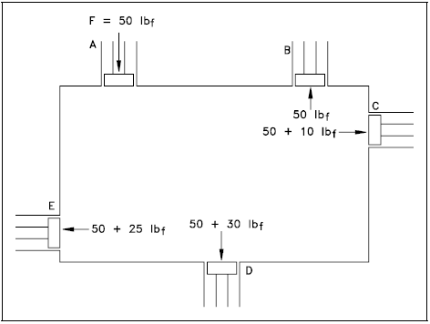
The pressure of the liquids in each of the previously cited cases has been due to the weight of the liquid. Liquid pressures may also result from application of external forces on the liquid. Consider the following examples. Figure 2 represents a container completely filled with liquid. A, B, C, D, and E represent pistons of equal cross-sectional areas fitted into the walls of the vessel. There will be forces acting on the pistons C, D, and E due to the pressures caused by the different depths of the liquid. Assume that the forces on the pistons due to the pressure caused by the weight of the liquid are as follows: A = 0 lbf, B = 0 lbf, C = 10 lbf, D = 30 lbf, and E = 25 lbf. Now let an external force of 50 lbf be applied to piston A. This external force will cause the pressure at all points in the container to increase by the same amount. Since the pistons all have the same cross-sectional area, the increase in pressure will result in the forces on the pistons all increasing by 50 lbf. So if an external force of 50 lbf is applied to piston A, the force exerted by the fluid on the other pistons will now be as follows: B = 50 lbf, C = 60 lbf, D = 80 lbf, and E = 75 lbf.
This effect of an external force on a confined fluid was first stated by Pascal in 1653.
Pressure applied to a confined fluid is transmitted undiminished throughout the confining vessel of the system.

PDH Classroom offers a continuing education course based on this continuity equation reference page. This course can be used to fulfill PDH credit requirements for maintaining your PE license.
Now that you've read this reference page, earn credit for it!

Control Volume
In thermodynamics, a control volume was defined as a fixed region in space where one studies the masses and energies crossing the boundaries of the region. This concept of a control volume is also very useful in analyzing fluid flow problems. The boundary of a control volume for fluid flow is usually taken as the physical boundary of the part through which the flow is occurring. The control volume concept is used in fluid dynamics applications, utilizing the continuity, momentum, and energy principles mentioned at the beginning of this chapter. Once the control volume and its boundary are established, the various forms of energy crossing the boundary with the fluid can be dealt with in equation form to solve the fluid problem. Since fluid flow problems usually treat a fluid crossing the boundaries of a control volume, the control volume approach is referred to as an "open" system analysis, which is similar to the concepts studied in thermodynamics. There are special cases in the nuclear field where fluid does not cross the control boundary. Such cases are studied utilizing the "closed" system approach.
Regardless of the nature of the flow, all flow situations are found to be subject to the established basic laws of nature that engineers have expressed in equation form. Conservation of mass and conservation of energy are always satisfied in fluid problems, along with Newton's laws of motion. In addition, each problem will have physical constraints, referred to mathematically as boundary conditions, that must be satisfied before a solution to the problem will be consistent with the physical results.
Volumetric Flow Rate
The volumetric flow rate (\( \dot{V} \)) of a system is a measure of the volume of fluid passing a point in the system per unit time. The volumetric flow rate can be calculated as the product of the cross-sectional area (A) for flow and the average flow velocity (v).
$$ \dot{V} = A v $$
(3-1)
If area is measured in square feet and velocity in feet per second, Equation 3-1 results in volumetric flow rate measured in cubic feet per second. Other common units for volumetric flow rate include gallons per minute, cubic centimeters per second, liters per minute, and gallons per hour.
Example:
A pipe with an inner diameter of 4 inches contains water that flows at an average velocity of 14 feet per second. Calculate the volumetric flow rate of water in the pipe.
Solution:
Use Equation 3-1 and substitute for the area.
$$ \dot{V} = (\pi ~r^2) ~v $$ $$ \dot{V} = (3.14) \left({2 \over 12} ~\text{ft}\right)^2 \left(14 ~{\text{ft} \over \text{sec}}\right) $$ $$ \dot{V} = 1.22 ~{\text{ft}^3 \over \text{sec}} $$
Mass Flow Rate
The mass flow rate (\( \dot{m} \)) of a system is a measure of the mass of fluid passing a point in the system per unit time. The mass flow rate is related to the volumetric flow rate as shown in Equation 3-2 where ρ is the density of the fluid.
$$ \dot{m} = \rho ~\dot{V} $$
(3-2)
If the volumetric flow rate is in cubic feet per second and the density is in pounds-mass per cubic foot, Equation 3-2 results in mass flow rate measured in pounds-mass per second. Other common units for measurement of mass flow rate include kilograms per second and pounds-mass per hour.
Replacing (\( \dot{V} \)) in Equation 3-2 with the appropriate terms from Equation 3-1 allows the direct calculation of the mass flow rate.
$$ \dot{m} = \rho ~A ~v $$
(3-3)
Example:
The water in the pipe of the previous example had a density of 62.44 lbm/ft3. Calculate the mass flow rate.
Solution:
$$ \dot{m} = \rho ~A ~v $$ $$ \dot{m} = \left(62.44 ~{\text{lbm} \over \text{ft}^3}\right) \left(1.22 ~{\text{ft}^3 \over \text{sec}}\right) $$ $$ \dot{m} = 76.2 ~{\text{lbm} \over \text{sec}} $$
Conservation of Mass
In thermodynamics, you learned that energy can neither be created nor destroyed, only changed in form. The same is true for mass. Conservation of mass is a principle of engineering that states that all mass flow rates into a control volume are equal to all mass flow rates out of the control volume plus the rate of change of mass within the control volume. This principle is expressed mathematically by Equation 3-4.
$$ \dot{m}_{in} = \dot{m}_{out} + { \Delta m \over \Delta t } $$
(3-4)
where:
| Δm/Δt | = | the increase or decrease of the mass within the control volume over a specified time period |
Steady-State Flow
Steady-state flow refers to the condition where the fluid properties at any single point in the system do not change over time. These fluid properties include temperature, pressure, and velocity. One of the most significant properties that is constant in a steady-state flow system is the system mass flow rate. This means that there is no accumulation of mass within any component in the system.
Continuity Equation
The continuity equation is simply a mathematical expression of the principle of conservation of mass. For a control volume that has a single inlet and a single outlet, the principle of conservation of mass states that, for steady-state flow, the mass flow rate into the volume must equal the mass flow rate out. The continuity equation for this situation is expressed by Equation 3-5.
$$ \dot{m}_{inlet} = \dot{m}_{outlet} $$
(3-5)
$$ (\rho ~A ~v)_{inlet} = (\rho ~A ~v)_{outlet} $$
For a control volume with multiple inlets and outlets, the principle of conservation of mass requires that the sum of the mass flow rates into the control volume equal the sum of the mass flow rates out of the control volume. The continuity equation for this more general situation is expressed by Equation 3-6.
$$ \Sigma ~\dot{m}_{inlets} = \Sigma ~\dot{m}_{outlets} $$
(3-6)
One of the simplest applications of the continuity equation is determining the change in fluid velocity due to an expansion or contraction in the diameter of a pipe.
Example: Continuity Equation - Piping Expansion
Steady-state flow exists in a pipe that undergoes a gradual expansion from a diameter of 6 in. to a diameter of 8 in. The density of the fluid in the pipe is constant at 60.8 lbm/ft3. If the flow velocity is 22.4 ft/sec in the 6 in. section, what is the flow velocity in the 8 in. section?
Solution:
From the continuity equation we know that the mass flow rate in the 6 in. section must equal the mass flow rate in the 8 in. section. Letting the subscript 1 represent the 6 in. section and 2 represent the 8 in. section we have the following.
$$ \dot{m}_1 = \dot{m}_2 $$ $$ \rho_1 ~A_1 ~v_1 = \rho_2 ~A_2 ~v_2 $$ $$ \begin{eqnarray} v_2 &=& v_1 ~{\rho_1 \over \rho_2} ~{A_1 \over A_2} \nonumber \\ &=& v_1 ~{ \pi ~r_1^2 \over \pi ~r_2^2 } \nonumber \\ &=& \left( 22.4 ~{\text{ft} \over \text{sec}}\right) { (3 ~\text{in})^2 \over (4 ~\text{in})^2 } \nonumber \\ v_2 &=& 12.6 ~{\text{ft} \over \text{sec}} \end{eqnarray} $$
So by using the continuity equation, we find that the increase in pipe diameter from 6 to 8 inches caused a decrease in flow velocity from 22.4 to 12.6 ft/sec.
The continuity equation can also be used to show that a decrease in pipe diameter will cause an increase in flow velocity.

Example: Continuity Equation - Centrifugal Pump
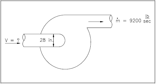
The inlet diameter of the reactor coolant pump shown in Figure 3 is 28 in. while the outlet flow through the pump is 9200 lbm/sec. The density of the water is 49 lbm/ft3. What is the velocity at the pump inlet?
Solution:
$$ \begin{eqnarray} A_{inlet} &=& \pi r^2 = (3.14) \left[ 14 ~\text{in} \left({ 1 ~\text{ft} \over 12 ~\text{in} }\right) \right]^2 \nonumber \\ &=& 4.28 ~\text{ft}^2 \end{eqnarray} $$ $$ \dot{m}_{inlet} = \dot{m}_{outlet} = 9200 ~{\text{lbm} \over \text{sec}} $$ $$ (\rho A v)_{inlet} = 9200 ~{\text{lbm} \over \text{sec}} $$ $$ \begin{eqnarray} v_{inlet} &=& { 9200 ~{\text{lbm} \over \text{sec}} \over A ~\rho } \nonumber \\ &=& { 9200 ~{\text{lbm} \over \text{sec}} \over (4.28 ~\text{ft}^2) \left( 49 ~{\text{lbm} \over \text{ft}^3} \right) } \nonumber \\ v_{inlet} &=& 43.9 ~{\text{ft} \over \text{sec}} \end{eqnarray} $$
The above example indicates that the flow rate into the system is the same as that out of the system. The same concept is true even though more than one flow path may enter or leave the system at the same time. The mass balance is simply adjusted to state that the sum of all flows entering the system is equal to the sum of all the flows leaving the system if steady-state conditions exist. An example of this physical case is included in the following example.

Example: Continuity Equation - Multiple Outlets
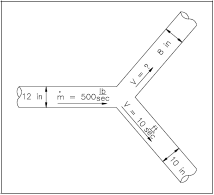
A piping system has a "Y" configuration for separating the flow as shown in Figure 4. The diameter of the inlet leg is 12 in., and the diameters of the outlet legs are 8 and 10 in. The velocity in the 10 in. leg is 10 ft/sec. The flow through the main portion is 500 lbm/sec. The density of water is 62.4 lbm/ft3. What is the velocity out of the 8 in. pipe section?
Solution:
$$ \begin{eqnarray} A_{8} &=& \pi ~\left[ 4 ~\text{in} \left({ 1 ~\text{ft} \over 12 ~\text{in} }\right) \right]^2 \nonumber \\ &=& 0.349 ~\text{ft}^2 \end{eqnarray} $$
$$ \begin{eqnarray} A_{10} &=& \pi ~\left[ 5 ~\text{in} \left({ 1 ~\text{ft} \over 12 ~\text{in} }\right) \right]^2 \nonumber \\ &=& 0.545 ~\text{ft}^2 \end{eqnarray} $$
$$ \begin{eqnarray} \Sigma ~\dot{m}_{inlets} &=& \Sigma ~\dot{m}_{outlets} \nonumber \\ \dot{m}_{12} &=& \dot{m}_{10} + \dot{m}_{8} \nonumber \\ \dot{m}_{8} &=& \dot{m}_{12} - \dot{m}_{10} \nonumber \\ (\rho A v)_{8} &=& \dot{m}_{12} - (\rho A v)_{10} \nonumber \\ v_{8} &=& { \dot{m}_{12} - (\rho A v)_{10} \over (\rho A)_8 } \nonumber \\ &=& { 500 ~{\text{lbm} \over \text{sec}} - \left(62.4 ~{\text{lbm} \over \text{ft}^3}\right) (0.545 ~\text{ft}^2) \left(10 ~{\text{ft} \over \text{sec}}\right) \over \left(62.4 ~{\text{lbm} \over \text{ft}^3}\right) (0.349 ~\text{ft}^2) } \nonumber \\ v_{8} &=& 7.3 ~{\text{ft} \over \text{sec}} \end{eqnarray} $$
PDH Classroom offers a continuing education course based on this continuity equation reference page. This course can be used to fulfill PDH credit requirements for maintaining your PE license.
Now that you've read this reference page, earn credit for it!

Source: https://engineeringlibrary.org/reference/continuity-equation-fluid-flow-doe-handbook
0 Response to "Continuity Equation Mass Transfer Continuity Equation Fluid Mechanics"
Publicar un comentario